Introduction to Reverse Engineering with radare2 Cutter
Part 2: Analysing a Basic Program
Saturday 17th November 2018
This is part 2 of a 3 part series on reverse engineering with Cutter:
- Part 1: Key Terminology and Overview
- Part 2: Analysing a Basic Program (You Are Here)
- Part 3: Solving a Crackme Challenge

The Cutter logo.
Cutter can be found on GitHub here: https://github.com/
Skip to Section:
Introduction to Reverse Engineering with radare2 Cutter
Part 2: Analysing a Basic Program
┣━━ Creating a Program to Analyse
┣━━ Static Analysis
┗━━ Part 3
Creating a Program to Analyse
I've put together a basic program that takes a number as an input, and outputs whether the number is odd or even.
Enter a Number (or q to quit): 2
2 is even.
Enter a Number (or q to quit): 1
1 is odd.
Enter a Number (or q to quit): 25
25 is odd.
Enter a Number (or q to quit): hello
Invalid Input
Enter a Number (or q to quit): q
If you wish to compile this yourself so that you can follow along with the analysis, I have included the C++ code below:
#include <iostream>
using namespace std;

int main(){
    string input;
    while(true){
        cout<<"Enter a Number (or q to quit): ";
        cin>>input;
        try {
            if (input == "q") {
                return 0;
            } else if (stoi(input) % 2 == 0) {
                cout<<input<<" is even.\n";
            } else {
                cout<<input<<" is odd.\n";
            }
        } catch(...) {
            cout<<"Invalid Input\n";
        }
    }
}
Save this to a file, then you can compile it like shown below:
$ g++ -std=c++14 -o outputfile inputfile
Static Analysis
After opening the file in Cutter using the default analysis settings, you will see the main interface with the disassembly view selected.
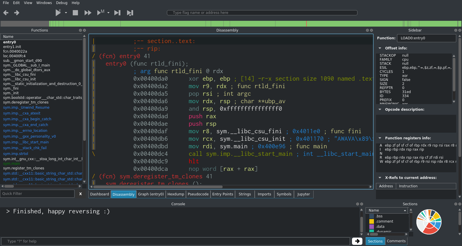
The first thing to do in most analysis tasks is to go to main. This is usually the best starting point for finding the code that you're interested in. For very simple programs (like the one we're looking at), most or all of the noteworthy code will be in main.
In Cutter, you can double-click main in the functions list on the left hand side. This will move the disassembler view to the start of main.
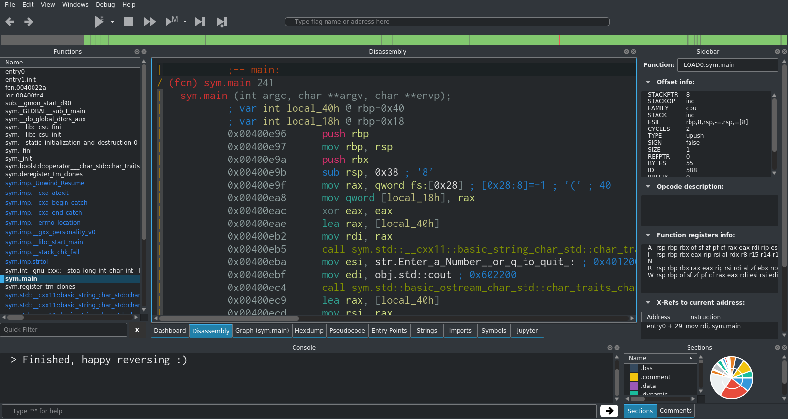
Immediately you can see the string for "Enter a number (or q to quit)". If you scroll down further, you will see the other key strings in the program too. This is a good indication that you've found something worth investigating further.
Next, you can click onto the graph view in order to see the execution flow of the program. Zoom out a bit so that you can see it all.
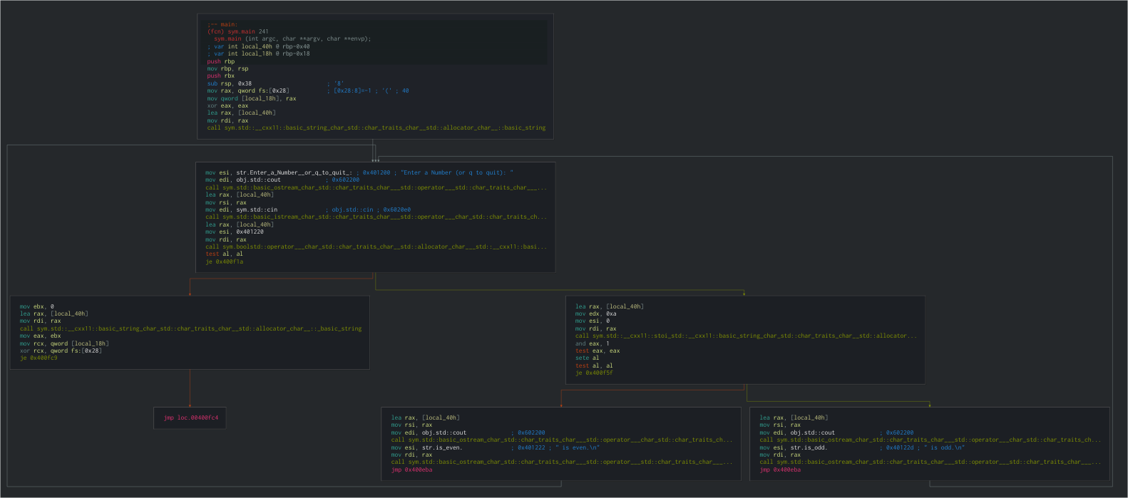
This is too small to read, but it gives you a basic idea of the various execution paths that the program can take, as well as showing the various loops.
If you zoom in on the second code block, you will see a clear human-readable string. Where possible, Cutter will automatically pick out the string values within functions and display them.
Immediately after the string, there is a reference to obj.std::cout, which is the standard output stream. This is a strong indication that something (probably the visible string) is been printed here.
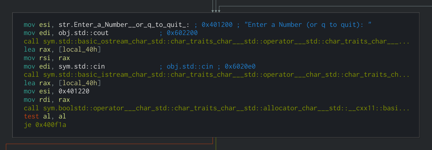
Next, there is a reference to obj.std::cin, which indicates that the program is reading from standard input. This is where you enter the number into the program.
This data is stored in a local variable on the stack which radare2/Cutter refers to as local_40h.
The memory address of this local variable is moved into rax using the lea (Load Effective Address) instruction, which is used to put a memory address from a source into the destination.
lea rax, [local_40h]
Since we're using the Intel syntax, rax is the destination and [local_40h] is the source.
In order to fully understand the instruction, you need to see the opcode, which you can find in the sidebar. In this case the opcode is lea rax, [rbp - 0x40]. There are two important things to note about this opcode:
- Square brackets: The second operand (source) is surrounded by square brackets. This is used to refer to the contents of the memory address stored in the register, rather than the memory address itself.
- Minus sign: The second operand also contains a mathematical operator and a hexadecimal value (in this example,
- 0x40). This is used to subtract a number of bytes from the memory address at the specified register, resulting in a new memory address. In this case, 0x40 in hex is 64 in decimal. The plus sign (+) can also be used.
Moving on, there is a test against the al register, followed by a je (Jump If Equal). If the jump does not take place, the program moves on to the error handling code which is part of the try/catch that is used.

While you wouldn't normally have the knowledge that a try/catch is used in a particular place, it is usually possible to make an educated guess based on the behaviour of the program. I'm going to cover more about this in my walkthrough for Sam's Crackme.
If the jump does take place (i.e. it hasn't caught yet), the program moves onto the next section. This is where it actually checks whether the inputted number is odd or even.

Firstly, the memory address of the user input stored in the stack is moved into rax again (as previously shown above).
lea rax, [local_40h]
The next important part is the call to stoi_std. stoi() is a C++ function to convert a string to an integer. Cutter has been able to detect that this function was used in the program and name it accordingly.
After that, the actual odd/even check takes place in the form of and eax, 1. eax is the lower 32 bits of the rax register, and 1 is the value to perform the bitwise AND operation against. The result of the AND will be stored in eax.
The use of the and instruction here may be unclear at first, however it is simply used to check whether the least significant bit of eax is a 1 or a 0. If it's a 1, then the number is odd, and if it's a 0, the number is even.
The traditional usage of and is to perform bitwise AND operations, for example:
0 AND 0 = 0
1 AND 0 = 0
0 AND 1 = 0
1 AND 1 = 1
...or with larger numbers:
    1101001101011101
AND 0101101010110001
    ━━━━━━━━━━━━━━━━
    0101001000010001
However in this case, the and instruction is used to perform a modulo operation (finding the remainder after a division).
Binary numbers ending in a 1 are always odd when converted to decimal. This fact can be exploited by and in order to quickly identify the parity of numbers without having to actually divide them by two and check the remainder.
All you have to do is AND the number against 1, which will perform a bitwise AND on the least significant bit. The output of the AND will be the parity of the number (1 for odd, 0 for even). For example:
    1001 (9 in Decimal)
AND    1 (Only Checking LSB)
    ━━━━
       1 (Odd)

    1110 (14 in Decimal)
AND    1 (Only Checking LSB)
    ━━━━
       0 (Even)
Going back to the analysis, you can apply this logic to the and eax, 1 instruction and see that eax will be 0 if the inputted number is even, and 1 if the inputted number is odd.
Moving on, the next few instructions are used to determine which output to show based on the result of the parity check (i.e. print number is odd, or print number is even).

After the and eax, 1 that I explained above, a test is performed on eax in the form of test eax, eax. This will perform a bitwise AND on eax against itself, and set the ZF, SF and PF flags accordingly.
test is identical to the and instruction, however instead of storing the result in the first operand like and does, test sets the appropriate flags and discards the result. In other words, it is a non-destructive and.
In the case of our analysis, eax can only be either 0 or 1.
- If
eaxis0,test eax, eaxresults in0, soZFis set. - If
eaxis1,test eax, eaxresults in1, soZFis cleared.
The next instruction is sete al. This sets the specified byte to 1 if ZF is set, and to 0 if ZF is not set.
al is the lower 8 bits of rax. In this section of the analysis, eax (which is the lower 32 bits of rax), is still set to either 0 or 1. This means that al is also either 0 or 1.
- If
ZFis set (which means thateaxwas0in the previoustest),sete alresults inalbeing set to1. - If
ZFis not set (which means thateaxwas1in the previoustest),sete alresults inalbeing set to0.
The effect that this has is flipping the least significant bit of eax/al. In other words, it's a bitwise NOT operation on the least significant bit. The reason that the not instruction is not used is that not performs a bitwise NOT on all of the bits, which is not the desired behaviour here.
The next instruction is another test: test al, al. As explained above, this performs a bitwise AND on the operands and sets the ZF, SF and PF flags accordingly.
In this section of the analysis, al is either 0 or 1
- If
alis0,test al, alresults inZFbeing set. - If
alis1,test al, alresults inZFbeing cleared.
Finally, there is a je instruction. This is what ultimately points the execution in the direction of printing $number is odd. or $number is even..
The je (Jump If Equal) instruction jumps to the location specified in the first operand if ZF is set. The opposite of this is jne (Jump If Not Equal), which jumps if ZF is not set. je and jne are usually used after a test or cmp (Compare), so the "If (Not) Equal" wording is referring to whether the result of the test or cmp was equal to zero, which is indicated by the status of ZF.
In the analysis, the location specified in the first operand is 0x400f1a, which is the offset for the section that prints $number is odd.. If the jump does not take place, execution continues on to print $number is even..
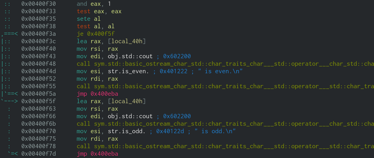
After the result is printed, there is a jmp (Unconditional Jump) to 0x400eba, which is the start of the loop - in other words it takes you back to the start and asks for another number.
The key section of this program is the part that determines whether the number is odd or even, and jumps accordingly. Just for reference, I have annotated an example execution below, with the inputted number being 1101 (13 in decimal, odd).
and eax, 1      //eax = 1101
test eax, eax   //1101 AND 1101 = 1101, 1101 != 0 so ZF is cleared
sete al         //ZF is not set, so al = 0
test al, al     //0 AND 0 = 0, 0 = 0 so ZF is set
je 0x400f1a     //ZF is set, so jump to 0x400f1a (print $number is Odd)
At this point, all of the noteworthy logic of the program has been successfully understood. With this knowledge, it would be possible to recreate the function of the program relatively accurately, which is often one of the main goals of reverse engineering.
Part 3
In part 3, we will solve a beginner level crackme challenge using Cutter and various other tools. If you'd like to get a head start, you can have a go at Sam's Crackme, which is the crackme that we'll be solving.